
Appearance
Output Setup
Outputs are the surfaces Exaplay 3 renders to. You create outputs — each with a size and a position — and assign them to screens. An output can be bound to a specific Windows display, bound to a machine and rendered purely by position + size, or left unbound for pre-planning.
Detected outputs
The engine enumerates the machine's connected monitors automatically — each appears on the Mapping to outputs tab of the panel under the STAGE canvas, named after the monitor Windows reports, with its detected resolution and desktop position, followed by the outputs of every remote machine under that machine's name. You don't need to add these by hand.
Adding an output manually
Use this to pre-configure an output (e.g. for a monitor that isn't connected yet) or to add an NDI stream.
- Open the STAGE tab.
- On the Mapping to outputs tab of the panel under the canvas, click + Output in the panel's bar (or + NDI for an NDI stream).
- Edit the new entry's properties (below) and it saves automatically.
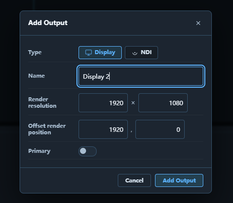
Output Properties
Select an output in the list to edit it:
| Property | Description |
|---|---|
| Name | The output's name, shown on its box on the Stage. Edited in the head row of the properties panel, next to the type icon — the same row the Produce & Play inspector puts a clip's name in |
| Type | Output (a monitor) or NDI (a network video stream) |
| NDI Name | Stream name advertised on the network (NDI type only; defaults to the first free Exaplay NDI N, and a name used twice is suffixed by the engine so two streams never share one). A Status line under it is the engine's own readback — streaming 1920x1080 @50 fps, canvas 1920,0, or why the stream is not sending |
| Resolution | Width × Height in pixels (ow × oh) |
| Position (px) | X, Y (ox, oy) offset within the desktop, for arranging outputs side by side / bezel correction |
| Splitting | Split one output into a grid of Columns × Rows cells, each assignable to a different screen. Works for a client's output too — set it from the master, the client applies and keeps it |
| Primary | Marks this output as the primary one |
| Assigned screen | The screen this output renders. This is the only thing that makes an output show content — an output with no assigned screen stays dark. The same control appears for remote (client) outputs, where the master writes it for you. A split output shows Assigned screens instead: one picker per cell, plus All cells to put the whole monitor on one screen. |
| Calibration channel | Pins a specific VIOSO calibration channel to this output, for rigs where the automatic channel placement guesses wrong. Leave it unset unless you have a reason; see Projection Mapping. |
| Colour correction | This projector's own Red / Green / Blue / Master trim, 0–100 % with 100 % untouched — for matching a wall of projectors whose lamps have aged differently. See Colour correction per output below. |
| Include in show | On by default. Switch it off to exclude an output from the show — e.g. the operator's GUI monitor, which is detected hardware but never plays content. Excluded outputs stay in the list (dimmed, not in show) but leave the Stage and a screen's output list, so assignment only offers outputs that actually belong to the show. Excluding an output clears its screen assignment. Works for local and remote outputs alike, and the setting survives monitor re-detection and client restarts. |
Creating outputs by hand
One word for one thing. This page says output throughout for the surface you create and assign to a screen — what older material sometimes called a "display" or a "virtual display". Whether an output is tied to a specific monitor is a property of the output, not a separate kind of object, so there is nothing to manage separately.
An output has a size and a position, and is assigned to a screen.
Adding one
- Open the STAGE tab.
- On the Mapping to outputs tab of the panel under the canvas, click + Output (or + NDI for an NDI stream).
- It is created at the default size 1920×1080, positioned to the right of the existing outputs so it does not overlap.
- Select its card to edit it: the Name in the panel's head row, Resolution and Position under More settings. The panel is the same inspector as in Produce & Play — a head row with the type icon and the name, then one card per section.
An output's Desktop position is a coordinate on that machine's own desktop — each machine starts at its own origin 0,0, so an output at 0,0 on the master and one at 0,0 on a client are both valid and independent. Don't type a "shared canvas" coordinate into a client output's position to push it next to a master's output — that value lands on the client's desktop. Cross-machine arrangement is handled for you (next section).
Cross-machine panorama
Assign outputs from different machines to the same screen and Exaplay composites them into one continuous surface — e.g. a panorama where the left half is driven by the master and the right half by a client. Across machines they are arranged automatically left → right by machine (master first, then each client), so a master output + a client output read as a single wide screen. Within a single machine, outputs tile by their desktop position until you lay them out on the Stage yourself (see Arranging below). See Multi-Client Setup for the networked workflow.
The workspace
The Stage tab's canvas is one zoomable workspace: the mouse wheel zooms about the cursor, Alt + drag (or a drag with the middle mouse button) pans — a plain drag on empty canvas does nothing, so a missed grab never moves the view — and the % button in the header fits everything back into view. The header names what you are looking at — Mapping · outputs on the show canvas, Screens · each screen as its canvas, Fields · placed on the screen canvases — and the picture never moves when you switch tabs: a screen's canvas sits exactly where its outputs are. Selecting anything — an output, a screen, a field — opens its properties in the panel on the right (the same place the Inspector lives in the Produce and Play tabs). The ? button next to the zoom controls opens a short legend of what the boxes mean and how to work on them.
The panel under the canvas sits where the media pane sits under the timeline in the Produce tab. It has two tabs, in the order a show is built — the screens with the fields on them first, and last the outputs mapped onto the screens — and the tab you pick decides what the canvas shows — two different pictures, because an output and a screen are two different things. The panel opens on Screens & Fields; it remembers the tab you leave it on.
- Screens & Fields — the screens and their fields, one view. The canvas shows every screen as its own canvas — the surface its fields play in, at the screen's content size — with its fields on it, and no outputs at all. The fields are live: click one to edit it, drag it to move it, use its corner handles to resize and the handle above it to rotate. The screen is its badge — the name tab on the canvas's top edge — and the canvas beside its fields: click either to edit the screen, drag either to move the screen freely (a screen with outputs takes them with it; a screen without outputs simply moves on the Stage). The recenter icon in the header fits everything back into view, and Reset view… puts every moved screen back. The + in a screen's top-right corner assigns outputs to that screen — the same list as Output Assignment in its properties. + Screen in the bar adds a screen; + Field adds a field to the selected screen (the button names it). The panel lists the screens one under the other, each with its fields listed under it; drag a screen onto another screen to reorder the screens, or a field onto another field of the same screen to reorder the fields — the top field renders on top. A screen that owns no output yet is parked on a shelf under the others, dashed.
- Mapping to outputs — the outputs. The canvas shows every output of this machine and of every remote machine as a box, drawn where it sits on the show canvas, with each screen's coloured outline around the outputs it owns. This is where you configure outputs: click a box to edit it, click its chip to assign a screen, drag it to lay the outputs out (edges snap). On a rig of several machines each machine's outputs sit in a thin frame with the machine's name under it — drag the name to move the whole machine, click it to zoom to it. The panel lists the same outputs — this machine first, then each remote machine under its name; click a card to edit it, + Output / + NDI in the panel's bar add one, and Find output… narrows the list (see Many outputs below). NDI outputs appear in the Sends lane under the canvas (see below).
On Screens & Fields the fields are always live and the screen is its badge and its canvas: click either to edit the screen, drag either to move the screen, and click a field to edit that field. Selecting something on the canvas never switches the tab — the panel stays where you put it. Drag the bar between the canvas and the panel to resize it, or use the chevron to collapse it to its bar.
Reading the canvas. On Mapping to outputs, every output box shows its name and its resolution; a box on another machine also carries that machine's name. The outline of a box tells you what it will do:
| What you see | Meaning |
|---|---|
| Solid, tinted in a screen's colour, a small colour tile in the corner | An output assigned to that screen — it will show content. Hover the tile for the screen's name, click it to change |
| Dashed and grey, Assign… in the corner | An output not assigned to any screen — it will stay dark |
| A box divided into cells, each in its screen's colour | A split monitor. Its chip reads the screen's name when every cell shows one screen, per cell… when the cells differ (or some are still dark), Assign… when none is assigned; click it to set each cell's screen. Each cell is draggable on its own — see Arranging the cells of a split output below |
| A coloured outline with a tab | A screen, around the outputs it owns; the tab names it and its content size. A screen that owns nothing is not on Mapping to outputs |
| A thin grey frame with a machine's name under it | A machine (shown once the rig has two or more): drag the name to move all of its outputs together, click it to zoom to that machine |
On Screens & Fields:
| What you see | Meaning |
|---|---|
| A filled, coloured canvas with a faint grid and the screen's name across it | A screen, at its content size — where its outputs are on the show canvas. Its badge (the name tab on the top edge) or the canvas beside the fields edits the screen on a click and moves it on a drag; the + in its corner assigns outputs to it |
| A dashed canvas under the others | A screen that owns no output yet, parked on the shelf so its fields still have a home — drag it anywhere; Reset view… parks it again |
| A thin amber box on a canvas | A field — the area of the screen content plays in |
Assigning. On Mapping to outputs, every output box carries the tile / Assign… chip in its top-left corner. Click it to pick a screen. The same choice is available as Assigned screen in the output's properties, and in reverse from a screen's own output list (Output Assignment in the screen's properties). A split monitor is assigned per cell, and it works the same way: its chip opens a menu with one screen picker per cell plus All cells, its properties show Assigned screens — the same pickers, one per cell — and a screen's output list offers each cell as its own row. Local and remote (client) split monitors alike.
The properties panel shows the essentials first. For an output that is its name, its assigned screen, Include in show and Splitting — a splitter feeding several projectors off one graphics output is ordinary rig wiring, and until the grid is set there are no cells to assign, pin or trim. Everything else — type, render resolution, desktop position, position on the show canvas, calibration channel, colour correction — sits under More settings, which opens by itself whenever one of those is in use (a size override, a trim, a pinned channel). A screen shows its name, its outputs, its fields and the content mask, with size, projection calibration and manual warping folded below. A field shows everything about its box and its content in one card, Size, Position & Scaling (warp is the only thing folded below it): its Size and Position — switch the whole card between pixels and percent with the px | % buttons in its header — a Placement grid that parks the field in any corner, the middle or over the whole screen keeping its size, its Rotation and Flip, and then, under Scaling, how a clip is fitted into it — Content: Fit (inside the field, aspect kept), Fill (crop) (covers the field, aspect kept), Stretch (the field's exact size) or Keep resolution (the clip's own pixel size); Fill and Keep resolution add an Overflow switch (cropped at the field or spilling over it), Fit and Keep resolution an Align picker. A clip that has its own size or offset (set in the Layout Designer or the clip's Inspector) places itself and ignores the field's Content setting; the editor says how many of the field's clips do, and Follow the field resets their own size and offset so they fit the field again.
Fields on the canvas. A field is drawn inside its screen's canvas, in the screen's content space, so a field set to 50 % width is half the canvas. Press anywhere inside a field and drag to move it — the first press selects it, the same drag moves it; use the corner handles to resize and the handle above it to rotate. With Warp on, the warp grid and its control points are drawn on the field too. The fields are never locked: to edit the screen under them, click the screen's badge (or the canvas beside the fields).
Content mask. A screen's mask has its own editor: switch on Content Mask in the screen's properties and follow Open the mask editor… — it opens as a window over the workspace (Esc closes it).
Many outputs. A project can hold sixty outputs while its screens stay a handful, and the Stage is built for that. Names, chips and badges keep their size at any zoom — zooming in makes room around a name instead of making the name huge — and a box shows only what fits: a large box its name, resolution and chip; a small one its name and a colour tile; a tiny one (the whole rig fitted into view) nothing but its tint, with the name appearing when you hover it, drag it or select it. Zoom in, or use Find output… in the panel's bar: type part of a name, a machine, a screen or a resolution and the list narrows to the matches while every other box on the canvas dims; Enter selects the first match and zooms to it, Esc clears. The magnifier on a card zooms the Stage to that output, clicking a card brings its box into view (keeping your zoom), and clicking a box scrolls its card into view in the panel.
Arranging. On the Mapping to outputs tab the output boxes are draggable with magnetic edge snapping — Windows display settings, for the show canvas. It works on a single machine (lay your projectors out as they hang on the wall, whatever order Windows has them in) and on a multiclient master, where local and client outputs drag alike. On a rig of several machines, drag a machine's name (under its frame) to move all of its outputs as one block — they snap as one, and the machine's own layout is kept. While you drag, guide lines show which edge the box has snapped to. Dropping a box saves it immediately: there is no Apply button. A client never arranges — the layout is the master's.
A drag arranges the picture, not the wall. By default every screen lays its outputs out by itself (Canvas layout: Automatic in the screen's inspector — desktop positions, machines left to right), and dragging boxes only makes the Stage look like the room: nothing about what the projectors show changes. A box you moved away from where its screen places it wears a small view only tag, and the screen's outline on the Mapping tab stays where the wall really is. To make a screen render from the layout you arranged — a panorama across machines, a mosaic wired in a different order — set that screen's Canvas layout to Custom: its outline then follows the boxes, wears a custom tag, and the header's Layout: chip reads custom (click the chip to jump to that setting). Typing a value into Position on show canvas under an output's More settings puts its screen on Custom by itself — that field is the deliberate remap. Reset view… puts the boxes of automatic screens back where their machines put them and leaves a custom screen's layout alone; set that screen back to Automatic in its inspector to unmap it.
Arranging the cells of a split output. A splitter or mosaic processor feeds one output to several projectors or LED panels, and the shape it feeds them in is often not the shape they are hung in — a 2×2 mosaic driving four panels in a row is the everyday case. So the cells of a split monitor are draggable on their own: press a cell and place it anywhere on the show canvas, with the same snapping every other box has. Until you move one they sit flush in the monitor's own grid, which is what a split output has always looked like.
To turn a 2×2 into a 4×1 strip, drag the two bottom cells up beside the top two; they snap flush, and once the screen is on a Custom canvas layout its canvas becomes the strip (7680×1080 for four 1920×1080 panels — the screen's tab shows the new size). Dragging the monitor's name still moves the whole thing, cells and all, and Reset view… puts the cells of an automatic screen back into their grid.
Nothing about the hardware changes: each cell keeps its real desktop position, so the picture goes out of the same connector as before. Only which slice of the show it renders moves. A client's split monitor arranges the same way from the master, and the layout is stored in the project, so it survives a reboot.
Which VIOSO placement rule the engine applied to a screen (vwf-mapping) and any channel that failed to load are reported in the screen's Projection Calibration section of the properties panel — the first thing to check when a projector shows the wrong slice.
Two different positions. Desktop position is where a window opens on a machine's own Windows desktop — detected hardware, and read-only for a client. Position on show canvas is the slice of the show the output renders. The second one is the value that moves the picture.
Sends
NDI outputs appear in a Sends lane under the canvas (on the Mapping to outputs tab) rather than as a rectangle on it. An NDI stream has no position on anyone's desktop, so placing it on the show canvas would put it at a coordinate that means nothing — and stretch the map around that coordinate, shrinking your real outputs.
A send is tinted by the screen it carries and behaves like any other output: click it to edit it in the panel on the right, and assign it a screen there. A send with no assigned screen is dashed and grey, exactly like an unassigned monitor — it will stream nothing. On the Screens & Fields tab the lane only says Sends are on the Mapping to outputs tab: sends are outputs, and that tab shows none.
What a send carries follows the same rule as a monitor: its own slice of the screen canvas, at its own resolution. A screen with only NDI sends streams the whole canvas. A screen that mixes monitors and sends lays each send out as a strip beside the monitors (the canvas grows to hold it), and the send streams exactly that strip — so a 1920×1080 send next to a 1920×1080 monitor is a 1920×1080 stream of the right-hand half, not a 3840-wide picture with the monitor in it. A screen may carry several sends; each is its own stream, and each costs a capture and an encode per frame, so the practical limit is what the machine can encode alongside playback. The Status line in the send's panel (and the pill's tooltip) says what is actually going out, including the canvas position of the slice; a red edge on a pill means the engine is not sending and the status names the reason. Sends are video only — no audio travels with the stream — and carry the screen's own 2D warp but not a VIOSO/dp calibration, which is applied to the projector window. The stream is opaque; a rig that composites the stream downstream and needs the canvas alpha sets ndi.send-alpha in the system configuration.
Colour correction per output
Projector lamps age at different rates, and two projectors of the same model rarely match after a season. Colour correction in an output's More settings is that output's own trim — Red, Green, Blue and Master, each 0–100 % with 100 % meaning untouched — applied by the engine that drives the projector. The swatch above the sliders shows what a full-white pixel comes out as, so you can compare it against the projector next to it.
It behaves like the colour menu on the projector itself:
- It is applied at the very end. After the screen is composed, after the 2D or 3D warp, and after a VIOSO calibration has drawn its channels — on the pixels that projector finally emits. Nothing about the show, the screen or the calibration changes.
- It trims down, never up. Matching a wall means bringing the brighter projector down to the dimmer one; there is no headroom above the pixel that was rendered, which is why the range stops at 100 %. For lifting the black floor of a blended edge, use the Black Level Editor instead.
- Each cell of a split output has its own. One graphics output feeding several projectors through a splitter is several lamps, so the cells are trimmed individually under the split preview.
- It belongs to the output, not to the show. It survives monitor re-detection, a client reboot and a show sync, exactly like Include in show and Assigned screen. A client's outputs are trimmed from the master's Stage; the value is stored on that machine and applied by its own engine.
- Untouched outputs cost nothing. An output left at 100 % stores no setting and the engine does no extra work for it.
Reset to 100 % puts the output (and its cells) back.
Previews do not show it. /stream/mjpeg, the Stage's Preview and the NDI sends all read the composed screen canvas, which is before this trim — the correction exists on the projector's own pixels, so the wall is where you judge it.
For a per-clip colour change — a source that is too warm in the content itself — use the clip's own colour correction in the Produce & Play inspector; see Effects.
Identify
Identify in the map header labels every output on the real wall with its name, the machine rendering it, its resolution and its pinned calibration channel — Windows' "Identify" for the whole rig. It answers "which projector am I looking at?" without unplugging anything.
On a multiclient rig it reaches the whole fleet: press it on the master and every paired client labels its own outputs too. It can also be driven from show control over OSC (/exaplay/global/identify on|off|toggle) — see External Show Control.
The labels are drawn over live content, so turn Identify off before going on air. It is a runtime switch, not part of the project: it is never saved into the show file.
Outlines
Outlines, next to Identify, is the same idea one level up: every screen draws its own box on the real wall, with its name, and every field on that screen draws its box and name inside it. Identify answers which projector is this; Outlines answers which rectangle of the picture is this — where a screen's canvas actually lands on the wall, and where the fields sit in it. It is the quickest way to check a field's placement while setting up, and the quickest way to see a field that has ended up off the screen.
Like Identify it reaches the whole fleet on a multiclient rig — press it on the master and every paired client outlines the screens it renders — and it can be driven from show control over OSC (/exaplay/global/showguides on|off|toggle), see External Show Control.
It is drawn over live content, so turn it off before going on air, and it is a runtime switch that is never saved into the show file.
Preview
Preview in the map header — offered on the Screens & Fields tab — draws the engine's live picture into every screen canvas: what the wall is showing right now, under the fields, so a field can be placed against the real content and a screen's canvas checked without walking to the wall. The Mapping tab shows hardware, not canvases, so the button is not offered there.
It is off by default, and off it costs nothing — no picture is requested and nothing runs. On, it opens one small stream per screen from the engine you are connected to (a modest size and frame rate — a preview, not a monitor), so on a rig with many screens expect a little extra load on that engine while it is on. The pictures pause while the browser tab is hidden, and the setting is remembered per browser. A screen the engine cannot stream for a moment (while a show loads, for instance) shows no preview · retrying on its canvas and comes back on its own. While you drag a field the picture dims: it shows where the content was until the drop reaches the engine.
Multi-Screen Layout
Use the Mapping to outputs tab of the Stage to arrange the physical placement of outputs relative to each other — see Arranging above. Each screen's outline follows the outputs it owns.
Warp & Blend
Geometric warping and edge blending are configured per screen/field, not on the output itself. See Projection Mapping for full details.
Test Pattern
Use Generate Test Pattern to open an external test-pattern generator in a new tab — handy for producing colour bars / alignment cards to play back while configuring outputs.
Output-List File
The output configuration is stored in the project under project.system["output-list"]; a snapshot is also written to output/output-list.json. Each entry uses these fields:
json
[
  {
    "display": "display_1",
    "name": "Display 1",
    "type": "display",
    "ow": 1920,
    "oh": 1080,
    "ox": 0,
    "oy": 0,
    "col": 1,
    "row": 1,
    "primary": true,
    "owner": ""
  }
]| Field | Description |
|---|---|
display | Stable output id (e.g. display_1) |
name | The output's name |
type | display (a monitor), ndi, or region (an output bound to a machine by position + size) |
ow / oh | Width / height in pixels |
ox / oy | X / Y position on the desktop |
col / row | Cell index when the output is split (1-based) |
primary | Whether this is the primary output |
owner | Varname of the screen assigned to this output (empty if unassigned) |
ndi_name | NDI stream name (NDI outputs only) |