
Appearance
Projection Mapping & Warp/Blend
Exaplay 3 integrates with VIOSO for professional geometric warping and edge blending across multiple projectors.
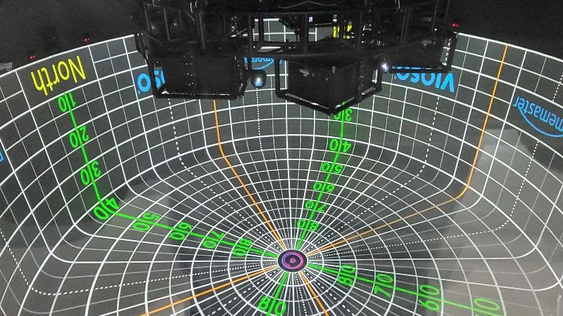
What Is Warp/Blend?
When multiple projectors cover the same surface (a curved screen, a building facade, or a multi-projector flat screen), two corrections are needed:
- Geometric warping — corrects lens distortion and keystoning so the image aligns with the physical surface.
- Edge blending — fades the overlapping region between adjacent projectors so the join is invisible.
VIOSO handles both using a calibration file (.vwf) produced by its auto-calibration software.
Loading a Calibration File
A calibration belongs to a screen (the canvas the projectors show), not to a single output.
- Open the STAGE tab and select the screen (its row on the Screens & Fields tab under the canvas, or the screen's badge on the canvas).
- In the inspector's Projection Calibration group, click VIOSO…. The VIOSO panel opens.
- Click Load… and choose the
.vwffile produced by VIOSO Calibrator. A multi-machine set (show_DC-1.vwf,show_DC-2.vwf, …) is picked by any one of its files and loaded as a whole. - The warp and blend are applied immediately. The panel's Status line says so.
Several calibration files on one screen
A screen can carry more than one .vwf. Use it when the wall was calibrated in separate runs — a projector added later, a section re-shot, or a per-machine export whose files are not a _DC-* set. The channels of all the files are used together, exactly as if they had come from one.
- Add… (next to Replace…) loads another file alongside the ones already there. Replace… swaps the whole calibration for a different one.
- The panel lists the files with the channel numbers each one brings — left.vwf · channels #0–#1, right.vwf · channel #2. The list order is the numbering order.
- ▲ ▼ reorder and ✕ removes.
Channel numbers are positions in the list
An output pinned to a Channel number means the n-th channel of the whole set, so anything that changes how many channels sit ahead of a file moves those pins. Adding a file is always safe — its channels are numbered after the existing ones. Removing or reordering is not: the panel says so above the list whenever this screen has outputs pinned by number, and after such an edit check the Outputs of this screen table, or press Pin all in order.
Every file of the list is copied to the clients, and each one is watched for changes, so a recalibration of any of them is picked up on its own. There is a limit on the total length of the paths (the VIOSO API takes about 3,000 characters), which is roughly a dozen files on deep network paths and many more on short local ones.
The VIOSO panel
Everything about a screen's calibration is in one place:
Status — whether the calibration is actually rendering. Applied — 6 channels, rule identity (green) is the normal state. File read, not rendered yet (blue) means the engine has not drawn a frame with it, usually because no output is assigned to the screen. Not rendered: … (red) names why the engine refused the file (missing DLL or
.ini, a broken file, a failed reload). Applied with problems (amber) lists channels that stay black. Refresh re-reads the engine's verdict.Reapply — rebuilds the warpers from the file on disk without waiting for the file to change. Use it after a recalibration written in place, or to get a known-clean state.
Details — two tabs. Geometry draws where every channel sits on the calibrating machine's desktop and which slice of the screen it samples, sums the set up (channels, machines, desktop area, content area covered, split) and lists every channel's header as VIOSO wrote it. Warp & Blend is the test pattern described under Seeing the warp below.
Warp… — the calibration's own warp and blend, drawn. See below.
Outputs of this screen — every output that shows this screen, this machine's and each client's, with the channel it renders (read back from the engine that draws it) and its Channel picker. Automatic lets the engine place the channels; pin one output when a projector shows the wrong slice, and the screen's other outputs take the channels left over. None takes an output out of the set: it renders nothing and claims no channel — see below. A pin that names a channel the calibration does not have is marked in red: that output renders nothing until it is changed.
Finding out which projector is which
Setting an output to None is the quickest way to untangle a wall whose automatic placement is wrong. An output left on Automatic is never idle — the engine hands it whatever channel nobody claimed — so switching one to None is the only way to take a projector out of the set and see what the others are actually being given. That projector goes dark, and with Identify on it says no channel (set) so nobody chases it as a fault. Put it back on Automatic (or on a channel) when you are done; the setting is stored in the project like any other pin.
The row of buttons above the table is the sorting kit:
Identify on wall — the Stage header's Identify, in the panel: every output labels itself on the real wall with its name, its machine and the channel it draws. The dot shows the switch is on; it is one switch for the whole rig.
Solo (per row) — light only this projector: every other output of the screen goes to None until you press Solo again or close the panel, when the previous pins come back. The soloed output keeps the channel it was drawing. This is the quick answer to "which projector is this row".
Pin all in order — output 1 gets channel #0, output 2 gets #1, and so on down the list; outputs past the last channel go to None. A pin places its channel at the output, whatever the file's own geometry says, so this lights every projector with exactly one channel — then swap the ones that are wrong with their pickers. Use it when Automatic leaves several outputs on renders no channel: that happens when the file's channel positions do not describe these outputs (a calibration re-assigned in an external tool, or exported for another desktop). The status line names it too — automatic placement gives N output(s) no channel.
Reach for it only when Automatic cannot be recovered. Letting the calibration place its own channels is the point of a
.vwf— on a dome you never want to think about which projector is channel 7 — and pinning replaces that with an order you have to get right by hand. When Exaplay can see that the automatic placement is fixable, the status line and the output's own row point at the fix instead (see Per-cell offsets below).All automatic — release every pin on the screen.
Channel shapes (a fold under the table) — a small picture of every channel's warp and blend, read from the file: the trapezoid that leans left is recognisable on the wall, so this is the lookup table for the inverse question, which projector is channel 3. Click a shape to see it large in the Warp view. Each channel costs the engine a short read of the file, which is why the fold is closed until you open it.
Placement rules — a fold, closed, holding the rules that decide how the channels are placed. You normally never open it: Exaplay picks the right rule from the file, and only the switch that can do something on this calibration is shown. Identity mapping (on by default) appears when the file names several machines, and matches each machine to the channels VIOSO recorded under its hostname. Absolute offsets (raw desktop positions) appears on a single-machine calibration. Per-cell offsets appears only on the calibrations it applies to, and the fold opens itself for it — see below.
Channels twice as far apart as they should be
Some VIOSO exports of a split display (a mosaic or splitter feeding several projectors from one output — typically a Collected compound export) write each channel at its own cell position. Exaplay normally expects the parent display's position plus the cell index, so on such a file it adds the cell offset a second time: the channels land about one cell further out at every step, several projectors get no channel, and Details shows a desktop roughly twice as wide as the wall — the file is fine, the positions in the dialog are not.
Exaplay recognises this. When it does, Details says so in the file's own numbers ("the set spans 24960 px where the split declares 13440 px"), each shifted channel shows the offset the file really carries next to the one Exaplay drew, and the panel's Placement rules fold opens itself on Per-cell offsets. Switching it on rebuilds the calibration straight away.
If the channels are pinned, set them back to All automatic afterwards — a pin places its channel at the output whatever the file says, so it hides whether the file's own geometry now lands correctly.
It is a setting of the machine, not of the screen or the file: every engine loads its own copy of the calibration and reads its own setting, so a client that renders this screen needs it set on that machine too. The same switch is in Settings → System as VIOSO: Per-Cell Split Offsets — that is where to set it on a client, which has no calibration panel of its own.
It is off by default, and in the VIOSO panel the switch is only shown on calibrations that look like this (or where it is already on), so there is nothing to decide on an ordinary file.
Channels that name different Windows displays are fine: where they sit on one machine at positions that would put those displays on top of each other, they cannot be separate displays, so Exaplay reads them as cells of one and offers the switch. A "Collected" export of several calibration runs normally looks exactly like that.
If the positions are doubled but no switch appears, Exaplay could not prove which channels belong to one split display — Details says so and names the case. That happens when the channels were calibrated on different machines (each machine has its own desktop, so the same numbers there mean nothing), when the file names no machine at all, or when the positions would sit side by side rather than overlap. The file then has to be re-exported so its channels agree on the display they share. Pinning the channels to the outputs is the way to run the show meanwhile.
The same Status line and, per output, a Renders: line also appear in the inspector without opening the panel, and the on-wall Identify labels show the channel each output draws.
Removing the calibration (the panel's Remove) returns the screen to the plain, unwarped output. There is no separate on/off switch: a screen either has a calibration or it does not.
Assigning channels to outputs — step by step
A .vwf carries one channel per projector. Every output that shows the screen draws exactly one of them, and normally the file decides which: VIOSO records where each channel sits on the desktop (and, in a multi-machine set, on which machine), and Exaplay places the channels from that. That is Automatic, and on a correct calibration you never touch it.
You reach for the tools below when a projector shows the wrong slice, when two projectors show the same one, or when one stays dark.
The picker and its three values
The Channel picker appears in three places and means the same thing in all of them:
| Where | What it covers |
|---|---|
| VIOSO panel → Outputs of this screen, column Channel | one row per output — this machine's and each client's; a split monitor has one row per cell |
| Output editor (STAGE, click the output) → More settings → Calibration channel | this one output |
| Output editor → Splitting → Calibration channel per cell | one small picker per cell of a split monitor (Auto / None / #n) — the same for a client's monitor in its remote editor |
| Value | What the output does |
|---|---|
| Automatic | The engine places a channel here from the file's geometry. An automatic output is never idle — if the placement leaves something over, it takes what is left, in list order. |
| #n ‹name› | A pin: this output draws channel n, and draws it at the output — the file's own position for that channel is ignored. As soon as one output of a screen is pinned the screen's rule becomes explicit; the other, unpinned outputs take the remaining channels in list order, so pinning one projector never blacks out its neighbours. |
| None — renders nothing | Takes the output out of the set: it draws nothing and claims no leftover channel. This is the diagnostic value — it is the only way to see what the other projectors are really being given. With Identify on, the dark projector says no channel (set). |
All three are stored in the project with the output, so they survive a reboot, a project load and a show sync — on clients too.
Working out which projector is which
- Open the VIOSO panel and read Status. Green Applied — N channels, rule … means the calibration renders; amber Applied with problems already names the output or channel at fault in its detail line.
- Read the Renders column: what each output is drawing right now, as reported by the engine that draws it.
- Switch Identify on wall on. Every projector labels itself with its output name, its machine and the channel it draws — the same information as the table, but standing in the room.
- Not sure which table row is which projector? Press Solo on the row: only that projector stays lit, every other output of the screen goes to None until you release Solo or close the panel (the previous pins come back by themselves).
- Not sure what channel 3 looks like? Open Channel shapes: one small picture of each channel's warp and blend. The trapezoid that leans left is recognisable on the wall. Click one to see it large.
- Now fix it — the smallest change first:
- One projector is wrong → pin that output to the right channel and leave the others on Automatic; they take the remaining channels by themselves.
- Several are wrong, or several show renders no channel → Pin all in order (output 1 → #0, output 2 → #1, …), then swap the pairs that landed wrong with their pickers. Use this when the file's geometry does not describe these outputs at all (a calibration re-assigned in another tool, or exported for a different desktop). If the status line offers Per-cell offsets instead, take that: it restores the automatic placement, which pinning cannot.
- Back to square one → All automatic releases every pin on the screen.
- Check: Renders shows one channel per output, Identify agrees on the wall, Status is green. Switch Identify off and save the project.
What the Renders column says
- #3 ‹name› — the output draws that channel.
- renders no channel — automatic placement gave this output nothing; the status line names the remedy (see Channels twice as far apart above, and Pin all in order).
- None — renders nothing (set here) — a deliberate None, not a fault.
- pinned to #7, which this calibration does not have — a pin left over from a calibration with more channels; the picker shows it in red. Change it.
- not reported yet / not reported by the client yet — that engine has not drawn a frame with the calibration (no output assigned, or a client that is still loading).
On a client
A client's rows are locked on the client itself (Locked: outputs of other machines are managed on the master). Set pins on the master; the client adopts them with the next sync or project load. What a client renders is read from the client's own engine — it is that machine's answer, not the master's guess.
Seeing the warp — Warp…
The panel's Warp… button draws a test pattern through the calibration itself: one channel's real warp mesh and its real blend ramp, in the projector's own frame. It answers the question the header numbers cannot — did this calibration land the way it was measured — and it answers it without a show running, without an output window and without a projector attached, so a file can be checked the moment it is imported.
The picture is read out of the .vwf by VIOSO's own library, so it is the mapping the wall will get, not a drawing of the file's description of itself. On a master it also covers the channels a client renders: the calibration is synced byte-identical to every machine, so the master's copy is the client's copy.
What to look for:
- Orientation. The pattern carries TOP, BOTTOM and per-corner labels. A mirrored or rotated mapping shows here and in no number anywhere.
- Shape. Straight lines bending, a keystone, a circle going oval — the deformation the calibration applies.
- Blend. Dark edges are where VIOSO fades into the neighbouring projector. The summary under the picture names the darkest point; a channel in the middle of a wall that reports blend is fully open has no blend where it needs one. Switch Blend off to see the warp without it.
- Coverage. covers 92 % of the output means the mapping leaves the rest of that projector's frame black — correct for many physical setups, and worth knowing before the show.
Channel picks which channel of the file to look at, Detail how finely the mesh is sampled (a finer mesh shows a curved warp more accurately and takes longer to read), Mesh overlays the mesh's own triangles, and Reload reads the file again after a recalibration written in place.
This is a picture of the file. What the wall actually shows — the projectors lit, the overlap in the room — is still the room's answer; use the on-wall Identify labels and the output preview for that.
Projection Setup — warp, blend and black level per output
For a wall without a VIOSO calibration — two or three projectors on a flat or gently curved surface, a dome segment, a single projector that is not quite square to the wall — Exaplay has its own editor. It works per output: each projector gets its own warp grid, its own edge blend and its own black-level lift, exactly the way a projector's own menu would, and the result is drawn after the warp on that output's window alone.
Open the STAGE tab, select the screen, unfold Manual Warping in the inspector and press Projection Setup → Open editor. The editor lists every output the screen owns on the left — this machine's monitors (a split monitor's cells each count as their own projector) and each client's — and edits one at a time. Everything you change is on the wall at once.
Warp — corners first
Start with the Corners grid (the default): pull the four corners onto the surface and the picture is square. Then Refine to 3×3, 5×5 or 9×9 to pull the middle of the image — every point keeps its place, only new points appear between them. Spline smooths the mesh between the points; Linear keeps it straight; Perspective takes the four corners as a true perspective (straight lines stay straight everywhere, which is what a projector that is not square to the wall needs — a linear 2×2 bends the inside of a keystone). The canvas draws faint interior guides at a 2×2 so you can see the difference before the wall does.
The whole screen at once. The first row of the list, Whole screen, is one grid over the entire canvas, drawn on top of every output's own — bend the wall as a whole there (a gently curved surface, a picture that has to lean), and fix a single projector on its own row. The outputs are drawn faint on that canvas so you can see which projector a point lands on.
| Action | How |
|---|---|
| Select point | Click it, or Tab / Shift+Tab through the grid |
| Select several | Shift+click adds a point; drag on empty canvas to rubber-band a region; the handles left of and above the picture take a whole row or column (click selects, Shift adds); Ctrl+A takes all. Escape goes back to one point |
| Move point(s) | Drag any selected point, or a row / column handle, or the arrow keys — 1 output pixel per press; everything selected moves together. Alt while dragging moves a tenth of the mouse |
| Coarse / fine | Shift + arrows moves 10 px, Ctrl + arrows 100 px (PageUp / PageDown too), Alt + arrows 0.1 px — the step chip under the canvas shows which is armed while you hold the key |
| Type a position | The X / Y fields under the canvas, in output pixels — for a measured value |
| Pin one spot | Double-click the picture where it is wrong (or + Add pin, then click). Drag the pin's diamond and the picture follows it, fading out over the pin's radius; scroll over the pin to change the radius (or type R under the canvas); drag its small dot to move where the picture is held; Delete removes it. Several pins add up, and a pin never needs a finer grid |
| Straighten | The Warp card's Straighten button (takes the pins with it) |
A pin is the local fix a grid cannot give without going 9×9 everywhere: a bump in the plaster, one warped panel, a seam that is right except for a hand's width. It moves the picture at one spot by exactly the drag and by less and less out to its radius, so the correction stays smooth and the rest of the projector is untouched. Pins are applied after the grid, so refining or straightening the grid later leaves a pin on the wall feature it fixes.
Wall mode (header) draws the selected point as a crosshair on the projector it belongs to, so you can stand in front of the wall and nudge with the arrow keys without looking at the monitor. Bypass (header) shows the wall as if nothing were set — the before / after of every projector of this screen at once; press it again to put the setup back. The three chips beside it bypass Warp, Blend or Black on their own: look at the warp without the blend, or at the raw overlap without the lift.
Edge blend
Switch Enabled on. With Widths from layout on, each edge's width is read from how far this output overlaps its neighbour on the Stage canvas — arrange the two outputs so they overlap by the projected overlap and the blend is already right. Type a width to override one edge; that switches the layout rule off for that output.
Curve shapes the fade (2 is the usual smooth S, 1 a straight ramp) and Gamma is the projector's own (2.2 for most). The curve is drawn so that two facing ramps always add up to exactly one on the wall, whatever the curve — the seam disappears when the gamma matches the projector. Highlight blend zones paints every band on the wall in colour while you line things up.
A seam that is right in grey but breaks in one colour — a reddish or greenish band — is a projector whose red does not have its green's gamma (lamps age unevenly). Open Gamma per colour and trim that one channel; Same as gamma puts all three back. The curve preview draws the trimmed channels in their colour.
The Stage already knows where the seam is
When two outputs of a screen overlap on the Stage canvas and do not both blend, the screen editor says so ("Beamer L and Beamer R overlap by 240 px") and the Mapping lens wears a chip on the screen's frame. One click on either switches the blend on for both, widths from the layout — the editor is for fine-tuning after that.
The number in that sentence is a dial: type the overlap you measured on the wall (or nudge it with ↑ / ↓ — Shift ×10, Ctrl ×100) and the second output moves on the show canvas so the two overlap by exactly that. It is the same edit as dragging the box on the Mapping lens or typing its position, so the screen goes on a custom canvas layout and the blend bands follow. Read the overlap off the wall with the Vernier pattern below.
Black level
Projectors never go fully black, so where two of them overlap the black is twice as bright as where one lights the wall alone — and where four meet in the corner of a 2×2 wall, four times. Lift raises the black where this projector lights the wall alone; set it so that area matches the brightest overlap. With Balance overlap zones on (the default) every zone in between follows automatically: on a 2×2 wall each projector adds a third of the lift into the bands where two overlap and nothing into the corner where four do, so the whole wall ends at one black. The canvas labels every zone with how many projectors light it and its share of the lift. Feather softens each step between zones. Switch the balance off for the classic rule — the single-lit area lifted, every band left alone. Lift zone per edge lets a zone be wider or narrower than the blend band when a bright seam or a dark gap remains. The Tint matches a projector whose black is not neutral.
On the wall
Pattern replaces the show while you set up (drawn through the warp like real content): Grey 50 % is the seam test — a blend that is uniform at mid grey is right at every level a picture is likely to have; Grey steps shows four levels at once (10 / 30 / 50 / 100 %), so a wrong black level shows in the dark stripe and a wrong gamma in the bright one; grid + circles, a checkerboard and a colour ramp are there for the warp. Vernier is the overlap check: inside every blend band both projectors draw fine stripes, one at 6 px and the other at 6.3 px, so a fringe of darker bars appears across the band and moves 20 px for every pixel the overlap is off (the second projector's pitch is the coarse one). Type or nudge the overlap in the screen editor until the fringe sits on the white centre mark — the two are the same reading at ×20 and ×1 — and the layout matches the wall to the pixel. Identify labels every output. The Band lens shows what this projector sends into each of its blend bands, magnified and live, read back from the engine — not the wall itself, but the one place the ramp's shape and a per-colour trim can be checked without walking up to the seam.
Copy setup takes another output's warp, blend and black level onto this one — mirrored left ↔ right (or top ↔ bottom) for the projector facing it, so a pair is set up once — and Blend curve → all puts this output's curve, gamma and colour trims on every other output of the screen, leaving their widths alone.
Undo / Redo work per output, Revert puts every output back to how it was when you opened the editor, and Reset this output clears its warp, blend and black level.
Fleet
Each machine keeps its own projectors' setup: the master edits a client's outputs in the same list, and the values travel with the show to that client and survive its reboot, exactly like an output's colour trim. One rule for a seam that spans two machines: each engine's auto widths see only its own projectors, so that seam is offered on the Stage ("… overlap 240 px — Blend them") and switched on with the layout's width written explicitly on both sides. Type the width yourself if you place the projectors without the Stage arrangement.
Field warp
Independently of the projector setup above, a field can carry its own warp grid — useful to fit a piece of content to an object rather than to correct a projector. Select the field on the Stage (Screens & Fields tab) and open Warp in the inspector: the grid (2×2 to 5×5) is drawn over the field on the canvas, points drag and nudge with the arrow keys, and Outlines in the Stage header draws every screen's and field's named box on the real outputs while you work.
Point-Based Warping (3D)
Behind Settings → Debug mode. A screen's own Point-Based Warping (3D) group offers 3D Warp → Open editor: a manual 3D pose warper. It sits next to Manual Warping rather than inside it because it is a different tool — nothing to drag point by point, a projector's pose solved instead from points you pick. Choose a surface model or import a GLB/OBJ mesh, place a virtual projector, and calibrate its pose from projected crosshairs. Revert and Reset to defaults work as in the Projection Setup editor. It is preview-quality, not yet production-ready.
Edge blending and the VIOSO calibration
A VIOSO calibration carries warp, blend and black level for every channel inside the .vwf, measured by camera, and Exaplay applies them as-is — on a calibrated screen the manual blend and lift above are not drawn (the warp grid is not either), because the file already did that job better than a hand could. To adjust a calibrated blend, re-run or edit the calibration in VIOSO and load the new .vwf. The screen-level Blacklevel tools (base offset, overall lift, shape painter) stay in Exaplay and are applied before the calibration, so the VIOSO blend splits them correctly across the overlap.
Auto-Calibration (VIOSO)
If VIOSO AutoAlign is installed and a calibration camera is connected:
- Go to the Auto Calibration view (
/autocalibration). - Follow the on-screen wizard.
- The resulting
.vwffile is saved and loaded automatically.