
Appearance
LED Mapping
An LED processor takes an ordinary video signal (DisplayPort, HDMI, SDI) and cuts it into cabinets. That signal is almost never the picture the audience sees: a wing hangs turned, a ceiling strip is packed under the main wall, a column goes to another port, a door leaves a gap. LED Mapping builds the signal the processor expects from the screen's picture: it cuts the screen's canvas into cabinet arrays and places each one, pixel for pixel, where the processor reads it.
Only with Settings → System → Debug mode on — not yet production-ready. The mapping is saved with the show and still applies with Debug mode off; only the card and the editor are hidden.
Walkthrough
☰ menu → Walkthroughs → Outputs & projection → Mapping an LED wall maps a wall fed by two processor inputs: a main wall, a turned ceiling strip and a door, then the cabinet IDs on the wall — recorded from the real application. It is listed while Debug mode is on.
The idea in three words
| Term | What it is |
|---|---|
| Canvas | The screen's picture, at its content resolution — what your show draws. |
| Outputs | The signal that goes down the cable to the LED processor: the screen's outputs, side by side as they sit on the Stage. |
| Cabinet array | A block of cabinets that hangs together — a wall, a wing, a ceiling strip. It takes a rectangle of the canvas, at the cabinets' own pixels, and puts it into the outputs. |
An array is always 1:1: one canvas pixel is one LED. It can be turned in 90° steps and mirrored, never scaled. The outputs of the screen must be assigned on the Stage first; an array that lands outside every output is never sent.
Opening the editor
- Open the Stage and select the screen that feeds the LED wall.
- In the screen's inspector, open the LED Mapping card (tagged Debug). Its one line says what the wall gets now — "No mapping" until you set one up.
- Click Set up (or Open editor once a mapping exists).
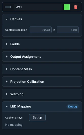
Once a mapping exists, the card also carries the mapping's on/off switch and the Cabinet IDs on the wall switch, so you can end the test pattern without opening the editor. While the pattern is on, the card stays open.
The editor
The editor works on a draft. Nothing reaches the engine until you press Apply; closing with unapplied changes asks first.
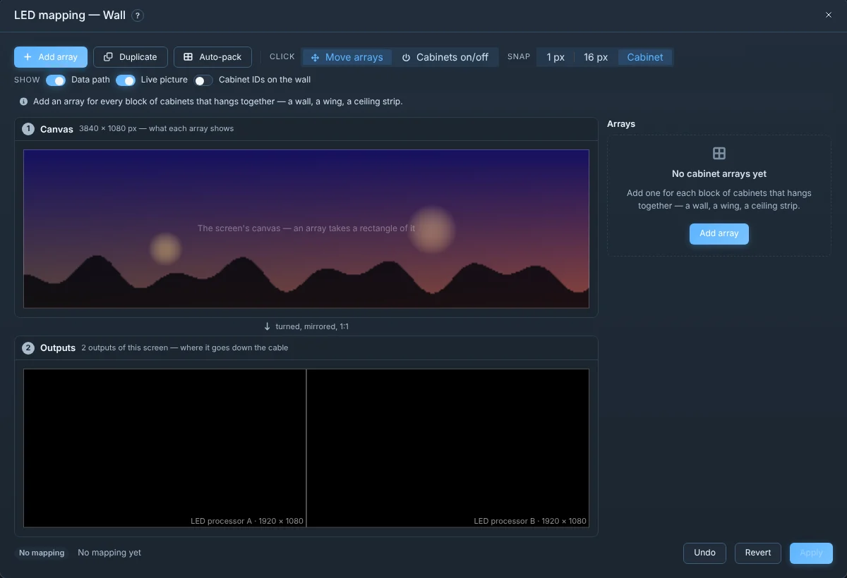
The toolbar reads left to right:
- Add array, Duplicate (a copy next to the selected array, in both views, named on from it — a wing is usually a copy of the other) and Auto-pack (packs every array into the outputs, tallest first, without gaps).
- Click — what a click in the views does: Move arrays, or Cabinets on/off (see Switching cabinets off).
- Snap — dragging steps by 1 px, 16 px or one Cabinet.
- Show — Data path (the cable route, below), Live picture (the screen's picture from the engine, in both views) and Cabinet IDs on the wall.
Under the toolbar, one line says what to do next and which keys work.
The two views, numbered as the picture travels:
- Canvas — the screen's picture. Each array's rectangle shows what it takes. Drag an array here to change what it shows.
- Outputs — the signal to the processor, with each output labelled. Drag an array here to change where it goes. With Live picture on, this view shows the picture as the processor will get it, through the draft — before you apply it.
Pointing at an array lights it in both views and in the list.
The list and the inspector on the right: every array with its size and an OK, Check or Conflict badge, and for the selected one:
| Section | What you set |
|---|---|
| Cabinets | Name, the cabinet Model, Columns and Rows. The head shows the physical size in metres. |
| Shows | Where on the canvas it takes its picture (X, Y). Fit to canvas fills the canvas with as many whole cabinets as fit, from the top-left. The head shows the resolution. |
| Goes to | Where in the outputs it lands (X, Y), Move to the corner of an output, Turned clockwise (0°, 90°, 180°, 270°) and Mirror (left to right, before the turn). The head names the output it sits on. |
| Processor ports | How many ports the array needs and how full each one is (see below). |
Below the inspector, the checks list what is wrong; click one to select the array it names. They warn when an array crosses the edge of an output or lies outside every output, when two arrays overlap in the outputs, when an array takes pixels from outside the canvas, and when every cabinet of an array is switched off.
The footer shows the state (Applied, Not applied yet or Mapping off) and a count of arrays, cabinets and ports (hover it for the pixel total). Mapping on switches the whole mapping off without deleting it, applied with Apply. Undo steps back through your edits in the editor, Revert returns to what is applied, Apply sends the draft, and Remove mapping deletes it after asking — the screen then draws its outputs as usual.
Cabinet models
The Model list offers common cabinets:
| Model | Cabinet | Pixels |
|---|---|---|
| 3.9 mm | 500 × 500 mm | 128 × 128 |
| 2.6 mm | 500 × 500 mm | 192 × 192 |
| 2.9 mm | 500 × 500 mm | 168 × 168 |
| 3.9 mm | 500 × 250 mm | 128 × 64 |
| 1.9 mm | 500 × 500 mm | 256 × 256 |
Take the pixel count from the cabinet's data sheet; it is what decides the mapping. The millimetres only feed the physical size.
Switching cabinets off
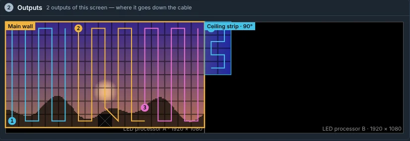
Choose Click: Cabinets on/off and click a cabinet in the Outputs view to switch it off — a door, a missing cabinet, a cut-out. It stays dark and the rest of the array carries on. Click it again to switch it back on, or press All on in the Cabinets section.
Data path and processor ports
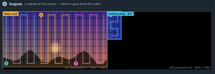
With Data path on, a coloured line runs from cabinet to cabinet in each array: the cable route, one colour per processor port, starting at the numbered dot. The route snakes up and down the columns from the bottom left, the commonest LED cabling.
Processor ports is a planning figure: one 1 GbE port carries about 655,360 pixels at 60 Hz and 8 bit, so the editor splits each array into ports and shows how full each one is. Ports are numbered per output, because each output feeds its own processor input. Check the real figure and the real cabling against your processor's software.
Keys
Click in a view first, so the keys go to the editor and not to a field.
| Key | Does |
|---|---|
| Arrow keys | Move the selected array by 1 px, in the view you last dragged in |
Shift + arrow keys | Move it by 16 px |
R / Shift + R | Turn it 90° clockwise / anticlockwise |
Delete | Delete it |
Ctrl + Z | Undo the last edit in the editor (only the draft; the show's own undo is not touched) |
Step by step: mapping a wall
The same rig as the walkthrough: one screen, Wall, 3840 × 1080, fed by two 1920 × 1080 outputs — LED processor A and LED processor B, each an input of the processor. The wall is a main block of 15 × 8 cabinets with a door at the bottom, plus a short strip hung sideways under the ceiling.
1. Add the main wall
Press Add array. The first array fills the first output with as many whole cabinets as fit: here 15 × 8 cabinets of 128 px, 7.50 × 4.00 m. In Cabinets, pick your cabinet's Model from its data sheet and set Columns and Rows to what hangs on the wall. The Canvas view shows the rectangle it takes from the picture, the Outputs view where it lands, and the list on the right reads OK.
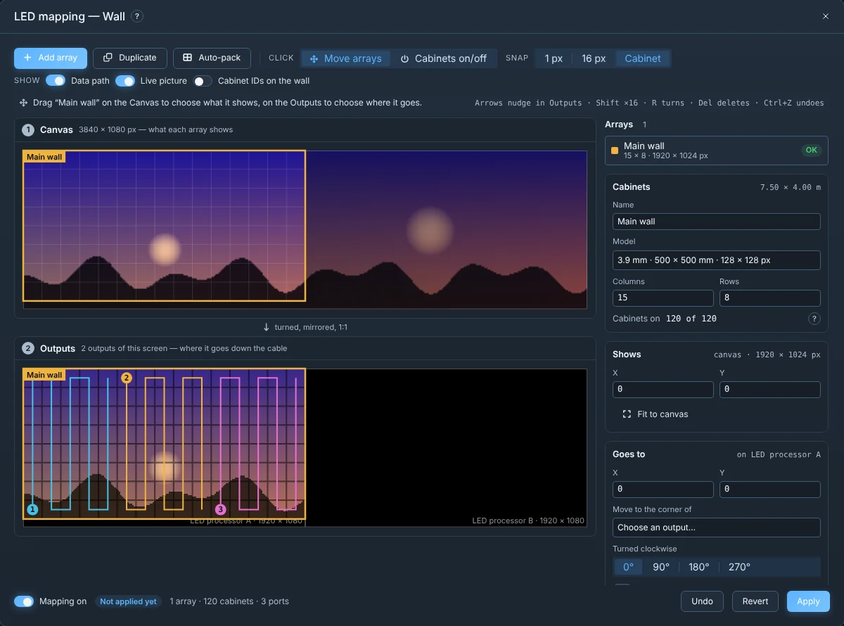
2. Add the ceiling strip and turn it
Press Add array again. A new array is packed into free space — here onto the second output. Give it a Name ("Ceiling strip") and its columns and rows (4 × 2). The strip hangs sideways, so in Goes to choose Turned clockwise → 90°: the processor gets it turned, and it reads upright on the wall. Mirror flips it left to right before the turn, for a strip hung from behind. The head of Goes to names the output the array sits on.
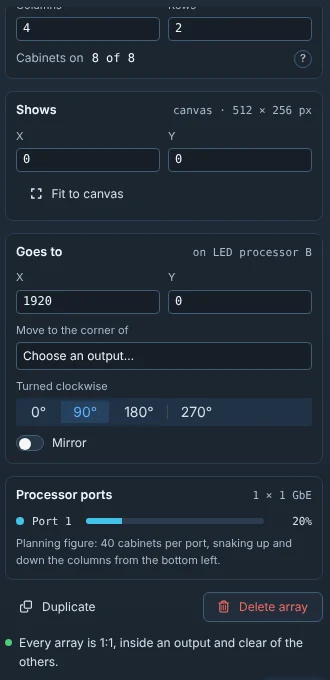
With Live picture on, the Outputs view shows the signal as the processor will get it, through the draft: the main wall on input A, the turned strip at the top-left corner of input B. The coloured line is the data path — the cable from cabinet to cabinet, one colour per processor port, starting at the numbered dot and snaking up and down the columns from the bottom left.
3. Switch a cabinet off for the door
Set Click to Cabinets on/off and click the cabinet where the door is, in the Outputs view. It is crossed out and stays dark; the rest of the array carries on, and the Cabinets section counts 119 of 120. Click it again to switch it back on, or press All on.
4. Apply
So far everything is a draft: the footer reads Not applied yet, and Ctrl+Z or Undo steps back through the edits. Apply sends the mapping to the engine. The footer then reads Applied with the count of arrays, cabinets and ports, and the checks under the inspector read clean: every array is 1:1, inside an output and clear of the others. If a check names a problem, click it to select the array it is about.

5. Read it off the wall
Switch on Cabinet IDs on the wall. The show on the LED wall is replaced by a test pattern in which every cabinet shows its label and an arrow pointing up — the crew reads off the real wall whether the labels run in order and every arrow points up, which is exactly when the mapping is right. The pattern stays on until you switch it off here or on the screen's LED Mapping card.

Checking it on the wall: Cabinet IDs
Cabinet IDs on the wall replaces the show on the LED wall with a test pattern: every applied cabinet shows its label, its array's colour, a border and an arrow pointing to the top of the picture. A label reads array, column, row: B3.2 is array B, column 3, row 2. The pattern goes through the mapping like the show does, so the wall reads right exactly when the mapping is right: every arrow points up, and the labels run in order.
The pattern stays on the wall until you switch it off — in the editor or on the screen's LED Mapping card. It uses the screen's one test-pattern switch, so it replaces any other test pattern on that screen.
Multi-client
A wall fed by several PCs is one screen spanning them, and the editor shows all of their outputs in one space, where the Stage arranged them. Each PC then sends only the cabinets that land on its own outputs; an array across two outputs is sent as two halves. A client decodes only the content its own cabinets show.
If two PCs' outputs were never arranged on the Stage, both sit at the same place and the editor warns about it. Arrange them on the Stage first. The mapping is part of the show and reaches every client like any other edit.
Limits
- Turns are in 90° steps and every array is 1:1 — no scaling, no free rotation. Scale the content on the canvas instead.
- A screen with a warp or a VIOSO calibration active draws that instead; the LED mapping applies to the plain output path.
- Whether a turned array lands the right way up, and whether two PCs' halves of one array meet without a tear, depends on the processor and on frame lock. Check both on the real wall with Cabinet IDs on the wall.
Related
- The Stage — screens, outputs and the screen's inspector
- Output Setup
- Projection Mapping
- Multi-Client Setup